As someone who started with a shop vac, upgraded to a cheap single-stage bag collector, and eventually installed a two-stage cyclone system with hard duct runs to every tool in the shop, I figured out how to handle what actually matters in shop dust collection. Today, I will share it all with you.
Dust Collection Basics
Dust collection works by creating negative pressure at the source of dust production. A collector motor creates airflow measured in cubic feet per minute (CFM). That dust-laden air travels through ductwork to the collector where particles are separated and stored. The piece that catches most people is that CFM at the collector is not the same as CFM at the tool — every foot of duct, every elbow, every gate creates friction loss that reduces actual airflow delivery. You have to design for what arrives at the tool, not what leaves the collector.
CFM Requirements by Tool
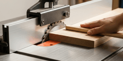
Each tool has a minimum CFM requirement for effective collection. Table saws need 350-400 CFM for the blade area. Planers want 400-500 CFM because they generate enormous chip volume in a short time. Jointers are in the 350-450 CFM range. Sanders need 200-350 CFM depending on size. Band saws are around 350 CFM. Size the branches for the tool requirements first, then work backward to the main trunk and collector capacity.
Collector Types
That is what makes dust collection endearing to us woodworkers — there is a clear progression from basic to better, and every stage makes a meaningful difference. Single-stage collectors draw debris directly through the impeller into a bag or drum. They are affordable and effective for small shops running one tool at a time. The limitation is that chips pass through the impeller, which reduces efficiency and requires frequent bag changes. Two-stage collectors use a cyclone separator to remove 95-99% of debris before it reaches the filter, extending filter life dramatically and maintaining consistent suction over time.
Single-Stage Considerations
Traditional bag-style collectors work well for occasional use and modest shop sizes. The standard 30-micron bags that come stock on most of these machines are genuinely inadequate — they pass fine dust right back into the shop air. Upgrading to 1-micron pleated filter bags is the single best improvement you can make to an existing single-stage machine. Position the collector where you can easily access and empty the bags without moving the machine. I am apparently someone who positioned my first collector in the corner most convenient for the duct run rather than most convenient for emptying, and the result was that I emptied it less often than I should have and the suction suffered for it.
Cyclone Advantages
Cyclone collectors separate the heavy debris fraction before it reaches the filter, which is where the real performance gains come from. The separator spins incoming air in a tight vortex — heavy chips fall out into a collection drum, clean air continues to the filter. Oneida and Clear Vue make the most popular aftermarket cyclone separators and both deliver significantly better performance than budget alternatives. The filter stays cleaner, maintains strong consistent suction, and handles the surges from a planer dumping chips without loading up and dropping performance mid-cut.
Ductwork Design
The ductwork is where the system succeeds or fails, and it is where most DIY installations underperform. Use metal spiral duct for main runs — the rigid smooth bore maintains airflow velocity where flexible hose loses it to friction and corrugations. Size your main trunk to handle total system CFM at 4,000 feet per minute velocity: a 2 HP collector producing 1,200 CFM needs a 6-inch main trunk. Larger collectors need 7 or 8-inch mains. Trunk lines should slope slightly toward the collector so chips do not accumulate in the horizontal runs.
Branch Lines and Gates
Branch lines connect individual tools to the main trunk. Use wye fittings rather than tee fittings — the wye creates far less turbulence and friction loss than a hard 90-degree tee. Blast gates at each tool branch let you close off unused tools, directing full system suction to whatever you are running. Keep branch runs short and avoid unnecessary elbows — each 90-degree elbow in a 4-inch branch is roughly equivalent to adding 5-7 feet of straight duct in friction loss.
Flex Hose Guidelines
Flexible hose is for the final connection between the fixed ductwork and the tool — nothing more. Keep flex hose runs to 6 feet or less. The corrugated interior creates turbulence that collapses airflow velocity; longer runs kill suction before the air gets to the tool. Smooth-bore flex hose is significantly better than corrugated where you can use it. Support any flex hose run longer than 3 feet to prevent sagging, which creates debris traps and further restricts airflow.
Grounding and Safety
Static electricity builds up in plastic components. Ground your ductwork by running a bare copper wire through the duct run and connecting it to your electrical system ground. Wrap copper wire around flex hose and tape it in place, connect the wire between metal duct sections. The investment is minimal and the peace of mind is real for anyone working with fine dust and solvent-based finishes.
Installation Tips
Mount hard duct securely to the ceiling or wall with metal strap hangers, spaced no more than 4 feet apart for 6-inch duct. Seal all joints with metal HVAC tape — not regular duct tape, which loses adhesion over time from vibration and temperature cycling. Include a cleanout access door at the low point of each horizontal run and anywhere the duct changes direction. Test the system with all gates open first to verify there are no major leaks, then check each tool branch individually with the other gates closed.
Jason Michael is the editor of The Workshop Journal. Articles on the site are researched, fact-checked, and reviewed by the editorial team before publication. Read our editorial standards or send a correction at the editorial policy page.


Stay in the loop
Get the latest the workshop journal updates delivered to your inbox.